Mind Machine Block I
Before we begin, I should tell you not to make or use one of these things if you have epilepsy or are sensitive to flashing lights. Should be common sense, but I like to be safe and remind people just in case. Also don't use this thing with your eyes open, close them and then turn it on. It's a little bright.
If you read my essay on mind machines you'll know a bit about the weird and largely abandoned technology. I mentioned how I had built one from a kit I ordered of Make: Magazine back in the day and am currently working on one using a RPi microcontroller. What I neglected to mention is I had done some experimenting with a visual-only machine a while back. Visual-only meaning it only flashed lights at you, no audio component for brainwave entrainment.
Even without the audio, you could see some fun red fractal patterns with other hues splashed in there if you ran the thing. I built it out of junk I had lying around in my apartment. Red LEDs, a 555 timer IC, some resistors and capacitors, a big switch I had gotten at a radio shack eons ago. The goggles were from a pair of costume goggles I had used for experiments in daytime IR vision and all of it was all thrown into a wooden sunglasses box I had bought at a junk shop.
The circuit was really simple, I'm a dogshit electrical engineer, and I'm sure there are at least 15 different ways to do what I was trying to do in a more elegant way, but it worked well enough. Here’s the schematic, I copied it out of my old notebook and slapped it into KiCad.
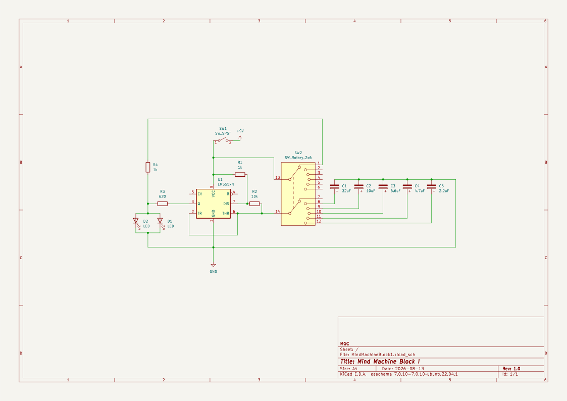
This thing worked by setting up a 555 as an astable oscillator. I think I learned how do do this in one of the circut textbooks I had lying around but the data sheet linked above explains how to set this up. Basically the frequency of the output on pin 3 is set by R1 and R2 values working in conjunction with the capacitor wired into pin 6.
$$f = \frac{1.44}{(R1 + 2\cdot R2) \cdot C}$$
We have R1 = 1k and R2 = 10k so by changing the capacitor values we can set the oscillation frequency. I had a rotary switch which I could use to select the capacitor in the circut, so I included five values, corresponding roughly to five brainwave frequencies. The sixth switch position simply dumped the power to the goggles directly, bypassing the 555 circiut entirely and kept the LEDs on constantly.
The five brainwave freqs I mapped were in the $\delta$, $\theta$, $\alpha$, $\beta$ and $\gamma$ brainwave ranges. From what I've read, the general trend is the lower the frequency the more relaxed you'll feel while the higher the frequency the more agitated you'll feel. Upper vs downer frequencies I guess.
The exact values were driven more by whatever caps I had in my parts pile rather than aiming for specific frequencies. As long as they were in the right range I was happy. If you decide to build something like this, feel free to use better cap values and narrow in your frequencies.
The duty cycle is defined by the resistors, R1 and R2 again.
$$D = \frac{R2}{R1 + 2\cdot R2}$$
So in our case we get a duty cycle of 47.6% which is close enough to 50% for our purposes.
The goggles were just the LEDs and a positive and ground wire that was connected to a 3.5mm jack. The jack then plugged into socket that was wired into point between R3 and R4 for the positive voltage and ground. Everything else was contained in the sunglasses box. I unfortunately don't have many photos, but these two should give you a sense of what I'm talking about. Forgive the amazon logo in the first photo and the overall terrible quality. I took these several years ago and the machine itself is on the other side of the planet right now.

To mount the LEDs in the goggles I just got some cardboard, cut out circular lens inserts for the goggles, poked holes in them to mount the LEDs, and replaced the goggles lenses with cardboard disks. Then, I mounted the LEDs in the holes and soldered everthing up, using hot glue at the end to keep the lights in place. The power switch, rotary switch to select the LED flash rate and the jack and socket for the goggles are visable too. I just used a drill to make the holes and then mounted the components.

The second photo shows the housing open, though I apologize for how dark the photo is. You can see the circuit board and the bank of capacitors that control the frequency. I used thick wire to attach the board to the rotary switch and it just 'hangs' in the box with not other attachment. The battery is friction fit with some scrap cardboard. Not pretty but it works.
To use the thing, just put the goggles on, close your eyes, hit the power switch, set your desired frequency and enjoy the light show. Adjust the frequencies and notice how the patterns change! I haven't used this thing for more than 5-10 minutes at a time so I wouldn't advise using it for longer than that. Be safe and have fun with it!
Thanks for stopping by!
JZ